
Background. For a drummer with a limited space, an Octopad comes very handy as it is a huge space saver. Moreover, there is an added advantage of you being able to practice with your Headphones and the whole neighbourhood can relax. I already have a ROLAND TD11 kit, however due to shifting and some space constraints, I am not able to utilize its full potential. Notwithstanding, there is one more thing to it, I wanted to do this from a long time.
Concept. After using all types of Drum Kits from DiY, Accoustic and Electronic, I personally like the Electronic kits for the numerous benefits it offers from being able to change the sound banks, flexibility, studio quality recording and so more.
I had an existing drum module of Roland TD11. The same is run by triggers in the drum pads in the form of Piezoelectric Sensors. The challenge is to now use external Piezoelectric sensors and mount them on a platform and interface with the TD11 Module. All external sensors when mounted in an ergonomical setup in the form of an Octopad will take us towards the construction of the Octopad.
Materials Used. The materials reqd for construction of the Octopad are as under
(a) Drum Module (I used the existing TD11 kit).
(b) DB25 Cable to interface the sensors and drum module.
(c) Piezo Electric Sensors – 20
(d) Aluminium Composite Panels/ Aluminium sheet 3 by 2 feet
(e) Rubber Mat (Existing Yoga Mat used)
(f) Rubber based adhesive
(g) Plywood/MDF/WPC board 3 by 2 feet
(h) Wires
(i) Soldering items
(j) RCA sockets -5
(k) Drum Sticks
(l) Hihat ( Existing HiHat of TD11 used)
(m) Bass/Kick Pedal (Modified my existing Pedal to install Trigger)
(n) HiHat Controller ( Existing HH Controller used )
(o) Snare Stand to mount the Octopad
(p) Tripod/stand to mount HiHat
(q) Floor Mat


Construction. The construction is mainly of the Octopad which is discussed in detail, balance is just interfacing the existing items and finally play the drum kit.
There will be a total of 8 triggers, all identical in size and characteristics. I have decided to make each trigger of Size 5 inches by 4 inches. Identical cuttings of quantity 8 are cut out of the ACP/Aluminium sheet and rubber sheet.
After cutting the sheet and rubber we pasted the rubber sheet on ACP with rubber based adhesive. This will be the striking side.


After preparing eight similar triggers, we used the same leftover rubber sheet to cut small 2cm by 2 cm size resting footpads quantity 32 @ 4 per trigger. These are used to give resting buffer to the trigger pad so that it does not interfere with the adjacent triggers and create a false beat.

On the rear side of the trigger plate will be the Piezoelectric sensor which is also mounted with the help of rubber based adhesive.
After assembling the trigger assemblies, the wires are soldered on each of the piezo sensors and after mapping the instruments to TD11 module, the wires can either be soldered or connected using the DB25 socket.
Having done that, I now used my existing Bass Drum Pedal from an old kit and attached it to base of WPC spray painted in black and clamped it. The piezo sensor was mounted on a 45 degree 3 inch by 3 inch wood triangle connected to an RCA socket.
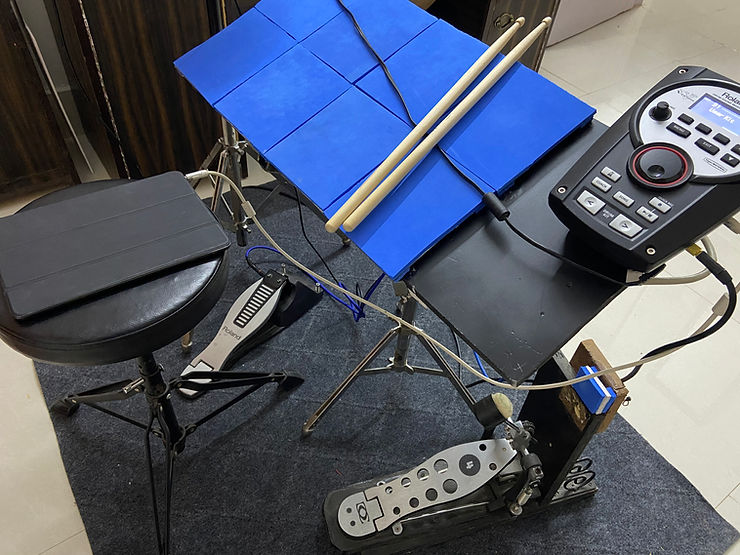
Here are some images of the completed Kit.