
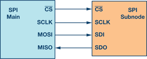
SPI stands for Serial Peripheral Interface, and it’s a way for electronic devices, like microcontrollers, to communicate with other devices, like sensors or displays. One device (i.e. Master) sends a puzzle piece to the other device, and then the other device(Slave) sends a puzzle piece back. They keep doing this until they have all the puzzle pieces they need to make sense of the message. SPI protocol uses four wires to send and receive information between devices. These wires are called MOSI(Master Out Slave In), MISO(Master in Slave Out), SCK (Serial Clock), and CS(Chip Select).
MOSI – The wire that the master device uses to send information to the slave device.
MISO – The wire that the slave device uses to send information back to the master device.
SCK – The wire that the master device uses to send clock signals to synchronize the transfer of data.
CS – The wire that the master device uses to select which slave device it wants to communicate with.
For communication, the master device sends a series of bits (0s and 1s) over the MOSI wire while sending clock signals over the SCK wire. The slave device sends a response back over the MISO wire once it receives these bits from MOSI. Each transfer of data is called a “transaction” and multiple transactions can occur in a row as long as the master device keeps the CS wire LOW to keep the slave device selected.
Once the master device is done communicating with a slave device, it raises the CS wire to deselect the slave and can move on to communicating with another slave device.
Overall, the SPI protocol is a simple and fast way for electronic devices to communicate with each other, and it’s commonly used in a variety of applications such as robotics, sensors, and displays.
Applications:
Memory devices: EEPROMs, Flash memory, and SRAMs to read and write data to and from microcontrollers.
Sensors: Accelerometers & Temperature sensors transfer data between the sensor and the microcontroller.
Displays: To communicate with displays like OLEDs and LEDs.
Communication modules: Wi-Fi and Bluetooth modules send and receive data wirelessly by using SPI protocol with mcu.
Motor control: Motor control applications to communicate with motor drivers.
How to use in Arduino??
Arduino has built-in hardware support for SPI communication.
On most Arduino boards, the SPI pins are labeled MOSI, MISO, SCK, and SS (or sometimes labeled CS).
The SPI.begin() function initializes the SPI communication.
The digitalWrite(SS, LOW) function selects the device to communicate with slave.
The SPI.transfer() function sends and receives data over the SPI interface.
The SPI.transfer() function is used to read the data from the EEPROM.
The digitalWrite(SS, HIGH) function deselects the EEPROM.
With the SPI library in Arduino, you can easily use SPI to communicate with many different devices and sensors.
Advantages of SPI
Faster than asynchronous serial communication and I2C
No start and stop bits
No slave addressing mechanism like I2C
Full duplex It has separate MISO and MOSI lines, so data can be sent and received at the same time
Not Limited to 8-bit data
The received hardware (slave) can be a simple shift register
Supports multiple slave devices.
Disadvantages of SPI
Requires more wires than other communication methods. (UART and I2C only require 2 lines)
No acknowledgment to inform that data has been successfully transferred
No error detection protocol
The communications must be well-defined in a function preferably
The master must control all communications (slaves can’t talk directly to each other)
It usually requires separate CS lines to each peripheral, which can be problematic if numerous slaves are needed
SPI only supports a single master
Can be used only for short distances
Example Arduino Code
SPI.begin() - To initialize SPI interface
SPI.setDataMode() - To send or recieve
SPI.setClockDivider() - To set clock divider
digitalWrite() - to send code to select the SPI device to send data to
SPI.transfer() - to send data
SPI.read() - to read data
SPI.write() -to send data without recieving any response
digitalWrite() - to deselect the selected device
#include <SPI.h>
int csPin = __; // CS pin of the SPI device
void setup() {
SPI.begin(); // Initialize SPI interface
pinMode(csPin, OUTPUT); // Set CS pin as output
digitalWrite(csPin, HIGH); // Deselect the device
Serial.begin(9600); // Initialize serial communication
}
void loop() {
digitalWrite(csPin, LOW); // Select the device
SPI.transfer(0x55); // Send data to the device
int response = SPI.transfer(0x00); // Receive data from the device
digitalWrite(csPin, HIGH); // Deselect the device
Serial.print("Response: ");
Serial.println(response); // Print the received data
delay(1000);
}In this example, the Arduino is communicating with an SPI device. It sends a data byte (0x55) to the device, then reads a byte of data from the device. The received data is then printed to the serial monitor. This process is repeated every second (1000ms) using the delay() function. Note that you may need to adjust the SPI mode and clock speed depending on the specifications of the device you are communicating with.